Marshall JCM2000 TSL Schematics
The JCM2000 TSL (Triple Super Lead) amps were introduced 1998. The whole JCM2000 range was probably discontinued in 2012.
JCM2000 TSL60 Triple Super Lead, 60W head
These 60W heads use 4x ECC83 and 2x EL34 tubes.
![]() Schematic of the TSL60 main board, TL60-60-02 Issue 5, (Marshall, 2001).
Schematic of the TSL60 main board, TL60-60-02 Issue 5, (Marshall, 2001).
![]() Schematic of the TSL60 main board, TL60-60-02 Issue 7, (Marshall, 2003).
Schematic of the TSL60 main board, TL60-60-02 Issue 7, (Marshall, 2003).
![]() Schematic of the TSL60 rear jack board, TL60-61-02 Issue 3, (Marshall, 1999).
Schematic of the TSL60 rear jack board, TL60-61-02 Issue 3, (Marshall, 1999).
 Bias instructions. The official Marshall biasing instructions for the JCM2000 DSL & TSL amps.
![]() Owners manual for the TSL60 amps.
Owners manual for the TSL60 amps.
JCM2000 TSL601 Triple Super Lead, 60W 1×12″ combo
These 60W 1×12″combos use 4x ECC83 and 2x EL34 tubes. These combos were fitted with a 12″ Marshall Celestion Wolverine WH-80-16 T5111 16Ω 80W speaker.
![]() Schematic of the TSL60 main board, TL60-60-02 Issue 5, (Marshall, 2001).
Schematic of the TSL60 main board, TL60-60-02 Issue 5, (Marshall, 2001).
![]() Schematic of the TSL60 main board, TL60-60-02 Issue 7, (Marshall, 2003).
Schematic of the TSL60 main board, TL60-60-02 Issue 7, (Marshall, 2003).
![]() Schematic of the TSL60 rear jack board, TL60-61-02 Issue 3, (Marshall, 1999).
Schematic of the TSL60 rear jack board, TL60-61-02 Issue 3, (Marshall, 1999).
Bias instructions. The official Marshall biasing instructions for the JCM2000 DSL & TSL amps.
![]() Owners manual for the TSL60 amps.
Owners manual for the TSL60 amps.
JCM2000 TSL602 Triple Super Lead, 60W 2×12″ combo
These 60W 2×12″ combos use 4x ECC83 and 2x EL34 tubes. These combos were fitted with two 12″ Marshall Celestion Wolverine WH-80-8 T5113 8Ω 80W speakers.
![]() Schematic of the TSL60 main board, TL60-60-02 Issue 5, (Marshall, 2001).
Schematic of the TSL60 main board, TL60-60-02 Issue 5, (Marshall, 2001).
![]() Schematic of the TSL60 main board, TL60-60-02 Issue 7, (Marshall, 2003).
Schematic of the TSL60 main board, TL60-60-02 Issue 7, (Marshall, 2003).
![]() Schematic of the TSL60 rear jack board, TL60-61-02 Issue 3, (Marshall, 1999).
Schematic of the TSL60 rear jack board, TL60-61-02 Issue 3, (Marshall, 1999).
Bias instructions. The official Marshall biasing instructions for the JCM2000 DSL & TSL amps.
![]() Owners manual for the TSL60 amps.
Owners manual for the TSL60 amps.
JCM2000 TSL100 Triple Super Lead, 100W head
These 100W heads use 4x ECC83 and 4x EL34 tubes. The TSL122 is the combo version of this head.
 iss1.gif) Schematic of the DSL100/TSL100 main board, JCM2-60-00 Issue 1, (Marshall, 1997).
Schematic of the DSL100/TSL100 main board, JCM2-60-00 Issue 1, (Marshall, 1997).
![]() Schematic of the TSL100 main board, TL10-60-02 Issue 1, (Marshall, 1997).
Schematic of the TSL100 main board, TL10-60-02 Issue 1, (Marshall, 1997).
![]() Schematic of the TSL100 main board, TL10-60-02 Issue 3, (Marshall, 1998).
Schematic of the TSL100 main board, TL10-60-02 Issue 3, (Marshall, 1998).
![]() Schematic of the TSL100 main board, TL10-60-02 Issue 4, (Marshall, 2001).
Schematic of the TSL100 main board, TL10-60-02 Issue 4, (Marshall, 2001).
![]() Schematic of the TSL100 main board, TL10-60-02 Issue 5, (Marshall, 2002).
Schematic of the TSL100 main board, TL10-60-02 Issue 5, (Marshall, 2002).
![]() Schematic of the TSL100 main board, TL10-60-02 Issue 7, (Marshall, 2003).
Schematic of the TSL100 main board, TL10-60-02 Issue 7, (Marshall, 2003).
![]() Schematic of the TSL100 main board, TL10-60-02 Issue 20, (Marshall, 2007).
Schematic of the TSL100 main board, TL10-60-02 Issue 20, (Marshall, 2007).
![]() Schematic of the TSL100 overdrive channel front control board, TL10-61-02 Issue 4, (Marshall, 1998).
Schematic of the TSL100 overdrive channel front control board, TL10-61-02 Issue 4, (Marshall, 1998).
![]() Schematic of the TSL100 rear / jack PCB board, TL10-62-02 Issue 6, (Marshall, 1998).
Schematic of the TSL100 rear / jack PCB board, TL10-62-02 Issue 6, (Marshall, 1998).
![]() Schematic of the TSL100 reverb / mains input boards, TL10-63-02 Issue 4, (Marshall, 1998).
Schematic of the TSL100 reverb / mains input boards, TL10-63-02 Issue 4, (Marshall, 1998).
![]() Schematic of the DSL100/TSL100 reverb & mains input boards, JCM2-63-02 Issue 7, (Marshall, 2005).
Schematic of the DSL100/TSL100 reverb & mains input boards, JCM2-63-02 Issue 7, (Marshall, 2005).
![]() Schematic of the DSL/TSL bias pot board, JCM2-64-00 Issue 1, (Marshall, 1997).
Schematic of the DSL/TSL bias pot board, JCM2-64-00 Issue 1, (Marshall, 1997).
![]() Schematic of the TSL100 clean channel, TL10-65-02 Issue 4, (Marshall, 1998).
Schematic of the TSL100 clean channel, TL10-65-02 Issue 4, (Marshall, 1998).
![]() Schematic of the TSL100 crunch channel, TL10-66-01 Issue 2, (Marshall, 1998).
Schematic of the TSL100 crunch channel, TL10-66-01 Issue 2, (Marshall, 1998).
Bias instructions. The official Marshall biasing instructions for the JCM2000 DSL & TSL amps.
![]() Owners manual of the TSL100 & TSL122 amps (1999).
Owners manual of the TSL100 & TSL122 amps (1999).
![]() Owners manual of the TSL100 & TSL122 amps (2004).
Owners manual of the TSL100 & TSL122 amps (2004).
JCM2000 TSL122 Triple Super Lead, 100W 2×12″ combo
These 100W 2×12″ combos use 4x ECC83 and 4x EL34 tubes. This combo is fitted with a 12″ Marshall Celestion Vintage and a 12″ Marshall Celestion Heritage speaker. This amp is the combo version of the TSL100 head. The TSL C212 extension cabinet goes very well with this combo.
Schematic of the DSL100/TSL100 main board, JCM2-60-00 Issue 1, (Marshall, 1997).
![]() Schematic of the TSL100 main board, TL10-60-02 Issue 1, (Marshall, 1997).
Schematic of the TSL100 main board, TL10-60-02 Issue 1, (Marshall, 1997).
![]() Schematic of the TSL100 main board, TL10-60-02 Issue 3, (Marshall, 1998).
Schematic of the TSL100 main board, TL10-60-02 Issue 3, (Marshall, 1998).
![]() Schematic of the TSL100 main board, TL10-60-02 Issue 4, (Marshall, 2001).
Schematic of the TSL100 main board, TL10-60-02 Issue 4, (Marshall, 2001).
![]() Schematic of the TSL100 main board, TL10-60-02 Issue 5, (Marshall, 2002).
Schematic of the TSL100 main board, TL10-60-02 Issue 5, (Marshall, 2002).
![]() Schematic of the TSL100 main board, TL10-60-02 Issue 7, (Marshall, 2003).
Schematic of the TSL100 main board, TL10-60-02 Issue 7, (Marshall, 2003).
![]() Schematic of the TSL100 main board, TL10-60-02 Issue 20, (Marshall, 2007).
Schematic of the TSL100 main board, TL10-60-02 Issue 20, (Marshall, 2007).
![]() Schematic of the TSL100 overdrive channel front control board, TL10-61-02 Issue 4, (Marshall, 1998).
Schematic of the TSL100 overdrive channel front control board, TL10-61-02 Issue 4, (Marshall, 1998).
![]() Schematic of the TSL100 rear / jack PCB board, TL10-62-02 Issue 6, (Marshall, 1998).
Schematic of the TSL100 rear / jack PCB board, TL10-62-02 Issue 6, (Marshall, 1998).
![]() Schematic of the TSL100 reverb / mains input boards, TL10-63-02 Issue 4, (Marshall, 1998).
Schematic of the TSL100 reverb / mains input boards, TL10-63-02 Issue 4, (Marshall, 1998).
![]() Schematic of the DSL100/TSL100 reverb & mains input boards, JCM2-63-02 Issue 7, (Marshall, 2005).
Schematic of the DSL100/TSL100 reverb & mains input boards, JCM2-63-02 Issue 7, (Marshall, 2005).
![]() Schematic of the DSL/TSL bias pot board, JCM2-64-00 Issue 1, (Marshall, 1997).
Schematic of the DSL/TSL bias pot board, JCM2-64-00 Issue 1, (Marshall, 1997).
![]() Schematic of the TSL100 clean channel, TL10-65-02 Issue 4, (Marshall, 1998).
Schematic of the TSL100 clean channel, TL10-65-02 Issue 4, (Marshall, 1998).
![]() Schematic of the TSL100 crunch channel, TL10-66-01 Issue 2, (Marshall, 1998).
Schematic of the TSL100 crunch channel, TL10-66-01 Issue 2, (Marshall, 1998).
Bias instructions. The official Marshall biasing instructions for the JCM2000 DSL & TSL amps.
![]() Owners manual of the TSL100 & TSL122 amps (1999).
Owners manual of the TSL100 & TSL122 amps (1999).
![]() Owners manual of the TSL100 & TSL122 amps (2004).
Owners manual of the TSL100 & TSL122 amps (2004).
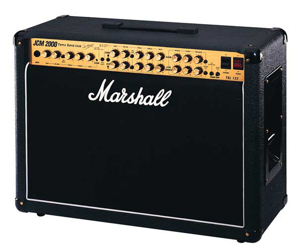 Photograph of a TSL122 combo.
JCM2000 TSL C212, 140W 2×12″ 16Ω extension cabinet
This 2×12″ cabinet is fitted with a 12″ Marshall Celestion Vintage and a 12″ Marshall Celestion Heritage speaker.
 Photograph of a TSL C212 cabinet.
Biasing the JCM2000 amps
Here are the official Marshall biasing instructions for the JCM2000 amps. I myself find the official bias settings too high and muddy sounding. I often bias the TSL amps to somewhat lower settings, often around 25mA – 30mA each tube (50mV – 60mV on bias connector) instead of the recommended 45mA (90mV). As this is very personal, I recommend trying this out for yourself and set the bias to what sounds best to YOU.
Bias instructions. The official Marshall biasing instructions for the JCM2000 DSL & TSL amps.